There are many good reasons for using a reference electrode. In this note, we report a few of them using the example of a lithium-ion battery comprising a lithium cobalt oxide (LCO) cathode and a graphite anode. All measurements were performed with a PAT-Cell, docked into a PAT-Stand-16 (both EL-Cell). The PAT-Stand-16 was connected to a Maccor series 4000 battery cycler used to control the cell current or cell voltage during the cc-cv cycles applied. Cell current, cell voltage, and both half-cell voltages were recorded in parallel by the data logger built into the PAT-Stand-16 docking station. The differential capacity data shown were derived during the experiment by the EC-Link data logger software.
1. Testing with two electrodes
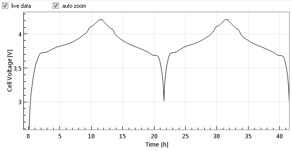
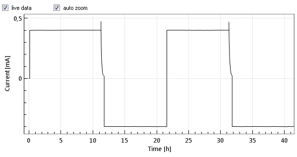
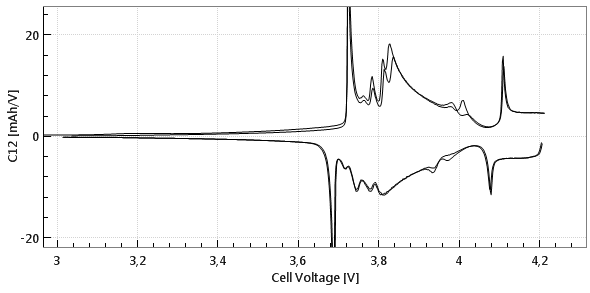
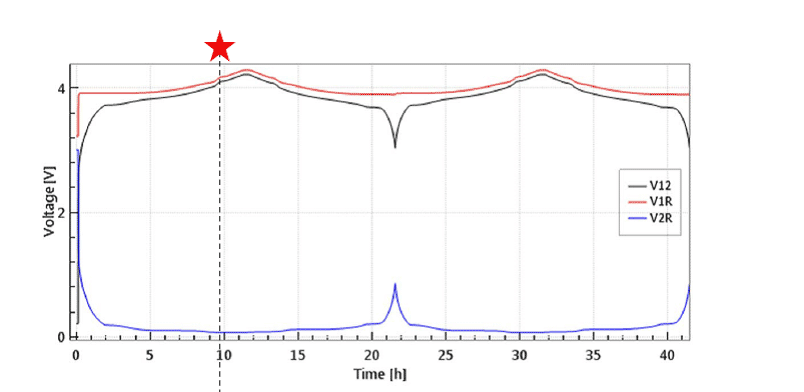
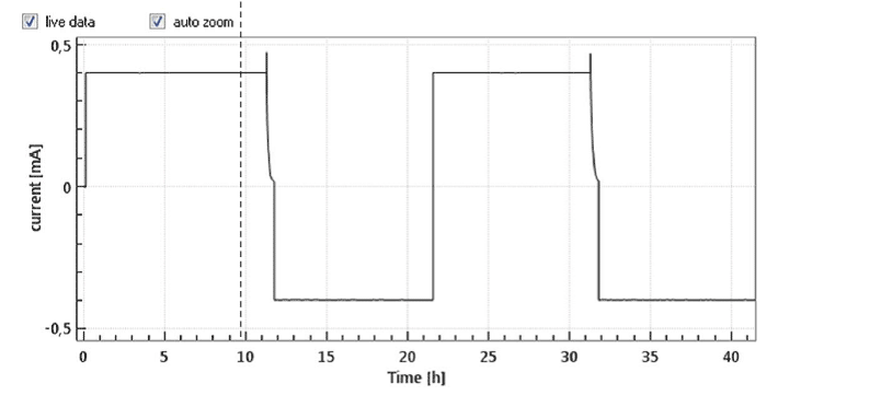
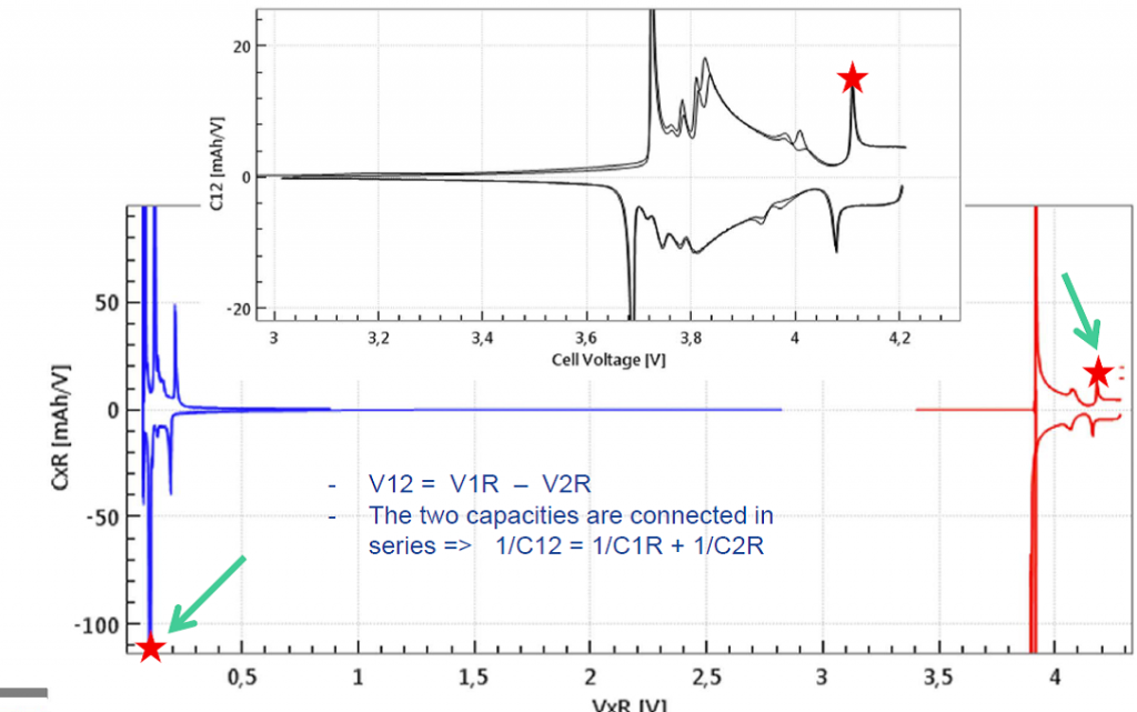
Commercial Li-Ion batteries come with 2 electrodes, e.g. lithium cobalt oxide (LCO) as the positive, and graphite as the negative electrode. Both electrodes are connected in series, that is, the current always flows through both electrodes, while the cell voltage can be considered as the sum of the voltage drops across the two electrodes and the separator in between. Figures 1a and 1b below show the cell voltage and current profile during the two initial charge/ discharge cycles. Figure 1c shows the differential capacity against the cell voltage, as calculated from the data shown in figure 1a and 1b.
Phase transitions in the anode and cathode cause the “steps and slopes“ in the full cell voltage graph. The steps turn into peaks when plotting the differential capacity C12 = ΔQ/ΔV12 against the cell voltage V12. However it remains unclear, which peaks refer to which electrode process.
2. Testing with three electrodes
When testing with a reference electrode, both half cells voltages are measured as well as differential capacities of both half cells can be derived. This way it becomes clear, which step refers to which electrode process. Noteworthy, in the equivalent circuit, the two half cell capacities are connected in series, C12 = (C1R * C2R)/(C1R + C2R). Therefore, a pronounced peak in the full cell capacity always refers to two simultaneous peaks in the two half cell capacities. Figures 2c illustrates this correlation for a given point in time during the cc-cv cycle.
3. Half-cells against Li-metal
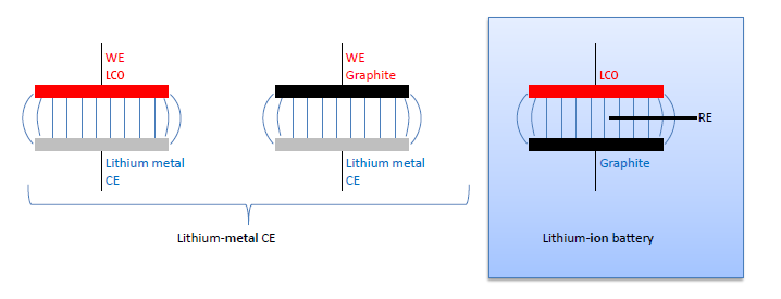
A common approach to avoid the use of a reference electrode, while still knowing the electrode potential on the lithium scale, is to build so-called half-cells. Here the full cell LCO vs. graphite is supposed to be represented by two “half cells” using lithium metal as the counter electrode (CE): LCO vs. lithium metal, and graphite vs. lithium metal (figure 3).
These “half cells“ are in fact full cells: Li-metal batteries. In case of very small currents the overpotential at the lithium metal counter electrode (Li-CE) can be neglected. Then the voltage LCO vs. Li-CE of the Li-metal battery equals the voltage LCO vs Li-RE of the LCO vs. graphite full cell. Half cells are often good for measuring the initial capacity of an anode or cathode material at low currents, however they have severe limitations: The Li-CE has a large SEI impedance at the beginning of the cycle experiment, typically much larger than the impedance of the working electrode. During cycling, the Li-CE is getting porous due to the growth of dendrites and so its impedance is dropping drastically. The fresh lithium surface is chemically reactive towards the electrolyte. Therefore, electrolyte additives cannot be explored with a Li-CE. Also, the lithium dendrites tend to grow through the separator, eventually causing an internal short circuit, and so determine the end of cycle life.
The large initial overvoltage of the Li-CE is illustrated in Figure 4 depicting the evolution of the full and half cell voltages of an LCO-Li “half cell” equipped with a Li metal reference electrode. Noteworthy, the large overvoltage at the Li-CE is causing a hump of the full cell voltage V12 at the beginning of the cycle. This artifact can only be identified thanks to the reference electrode.
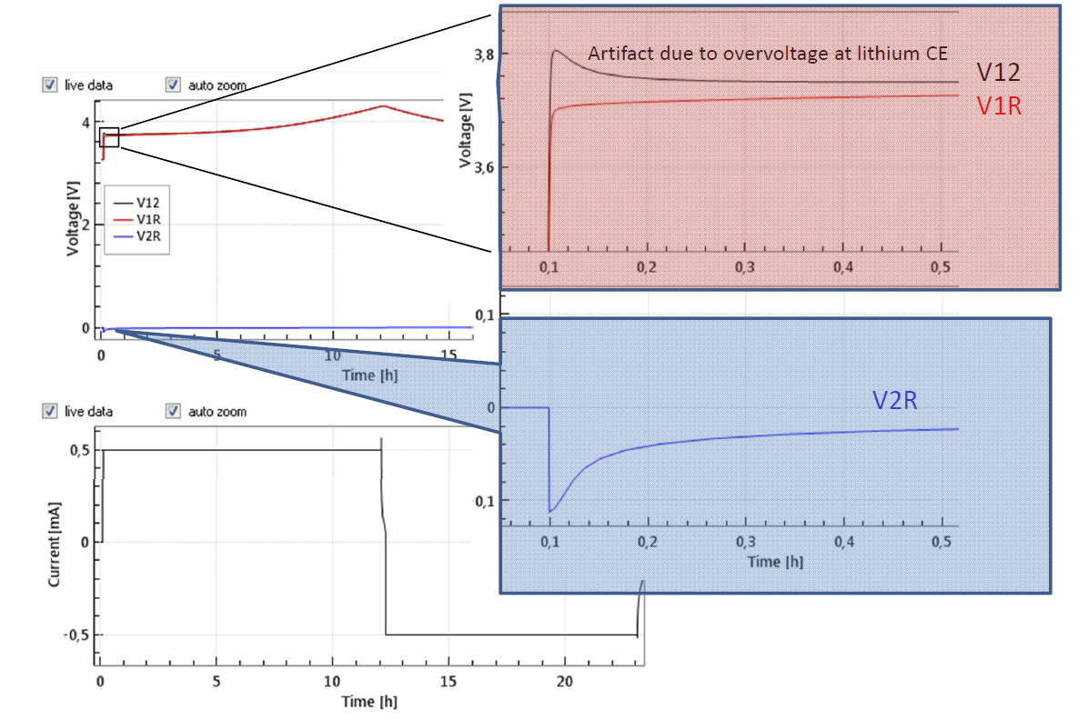
Figure 4: Half cell with LCO as cathode and Li-metal as anode and Li-metal reference electrode at 0.1 C
4. But when are half cells against Li-metal useful?
- Only with very small currents and if kinetics do not matter
Most often the Li-metal counter electrode shows a (far) higher impedance that the working electrode, e.g. LCO or graphite. This is true especially in the beginning of the cycling tests, when the lithium is not yet porous. During cycling dendrites are growing, so that the impedance of the Li-metal counter electrode drops dramatically.
- Only with few cycles and if aging does not matter
During cycling Li-dendrites are growing. They eventually kill the cell due to an internal shortcut. Thus when doing cycle tests, the growth of dendrites may limit the lifetime, rather than the aging of the working electrode.
- Only if the chemical reaction of Li-metal with the electrolyte does not matter
During cycling, the surface of the Li-metal is changing all the time due to stripping and plating. The fresh Li-metal surface is highly reactive towards the electrolyte. Remember the good reasons not to use a lithium metal anode in real batteries!
- Only if there is no chemical reaction between anode and cathode species
For instance, Mn ions dissolved from an NCM cathode are supposed to deteriorate the SEI growth on the graphite anode. This effect remains invisible, when using Li-metal instead of graphite as anode.
5. Lessons learnt
- So called “half cells” are in fact Li-metal batteries
- The large overvoltage at the lithium metal CE, the chemical reactivity of the porous lithium metal, and the growth of lithium dendrites render the “half cell” a poor model for lithium-ion batteries
- Whenever possible, use the “real” electrodes of the battery system under study, and employ a reference electrode in order to gain insight in what is happening at the individual electrodes.



Comments are closed.