Watch and download our product and tutorial videos:
EL-CELL Videos
Our Latest Video:
EL-Software: New Dashboard and Variable Passing in Version 3.1 (05/2026)
In this video, we will show the newest updates and changes in EL-Software version 3.1. It introduces a more streamlined, flexible workflow with a central dashboard, easier experiment continuation, and support for script restarts. It also improves scripting with finalised variable passing and other minor enhancements.
Electrochemical Dilatometer
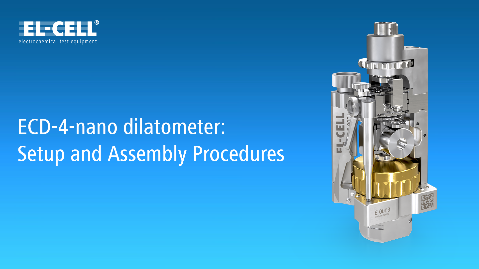
ECD-4-nano Setup and Assembly Procedures (04/2026)
In this video, we walk you through all the steps to set up and commission the latest version of the ECD-4-nano dilatometer (as of 2026).
Legacy content:
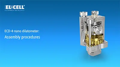
Assembly procedures of the ECD-4-nano electrochemical dilatometer (01/2023)
In this video, Dr. Matthias Hahn guides you through all the necessary steps to assemble the ECD-4-nano inside the glove box.
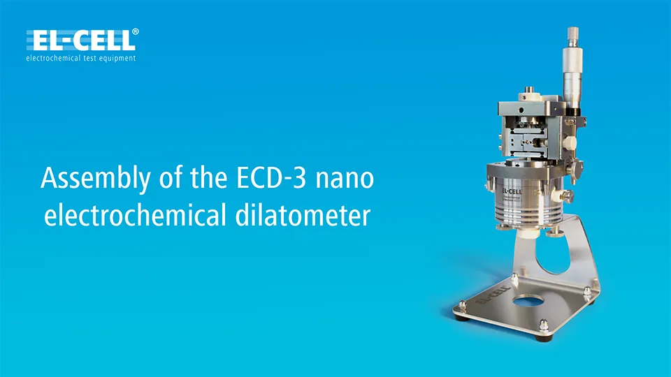
Assembly and disassembly of the ECD-3 and ECD-3-nano electrochemical dilatometer (04/2022)
In this step-by-step video tutorial, Dr. Matthias Hahn guides you through the assembly and disassembly of the ECD-3 and ECD-3-nano electrochemical dilatometer.
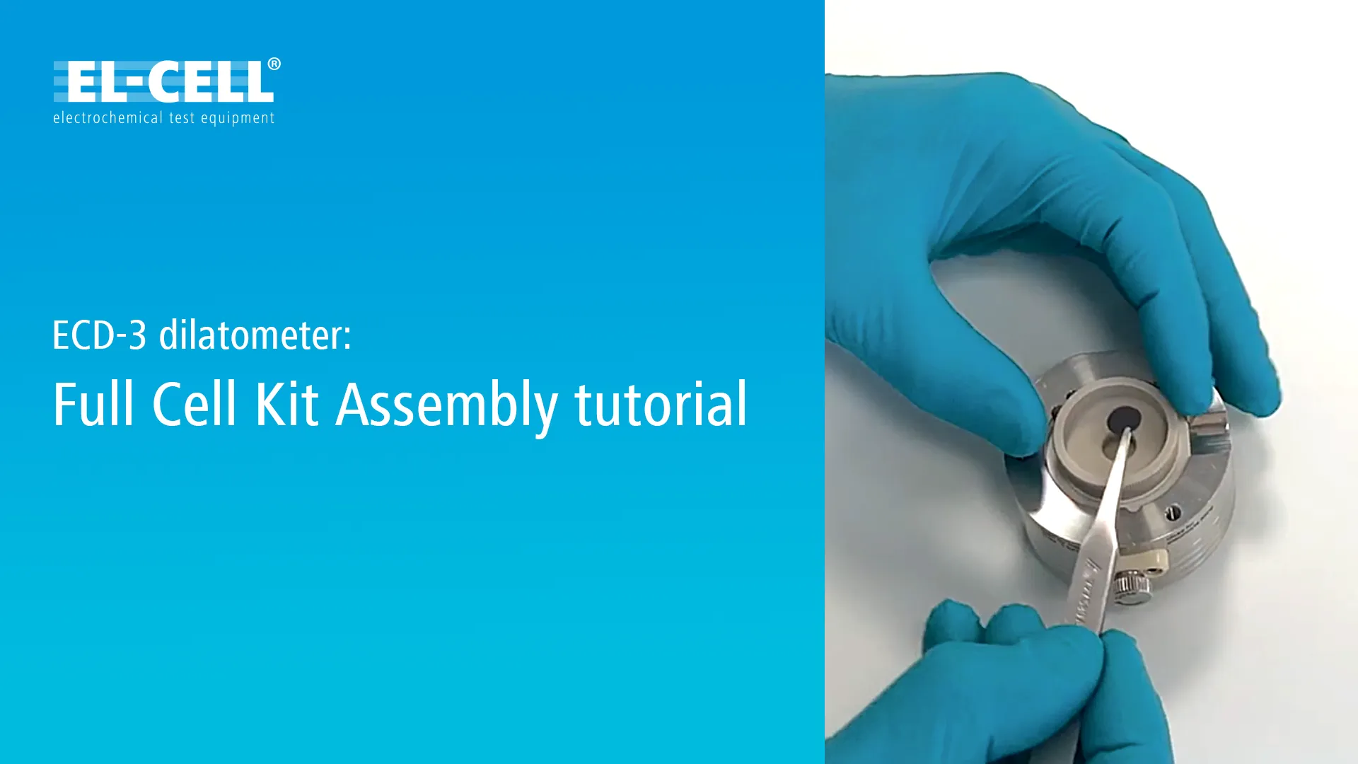
Assembly of the Full Cell kit for ECD-3 and ECD-3-nano electrochemical dilatometer (03/2022)
In this video, Dr. Matthias Hahn shows you how to assemble the parts of the Full Cell Kit for the ECD-3 dilatometer.
PAT Battery Testers
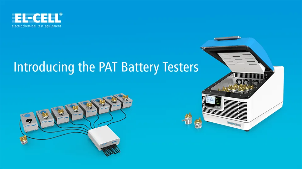
Introducing the PAT Battery Testers (10/2020)
In this video Dr. Matthias Hahn presents the new battery testers from EL-CELL and talks about the special capabilities and applications of the PAT-Tester-i-16 and the PAT-Tester-x-8.
Both devices offer fully equipped test channels with PStat/GStat and EIS capabilities and are specifically designed for battery material research with 3-electrode PAT-Cells and other small battery formats such as coin or pouch cells.
Unique features such as the Connection Matrix, which allows software-controlled switching of voltages or current flow between electrodes during operation, enable completely new and easier working methods in contrast to conventional devices from other manufacturers.
EL-Software
EL-Software: New User Interface (Version 3.0, 11/2025)
In this Feature Spotlight video, we will show the new web-based client and the user interface changes in EL-Software version 3.0. In this release, the client application has been replaced by a modern, web-based solution. This enables access to the EL software server via a web browser. At the same time, the user interface has been further optimized, offering improved clarity and numerous workflow enhancements.
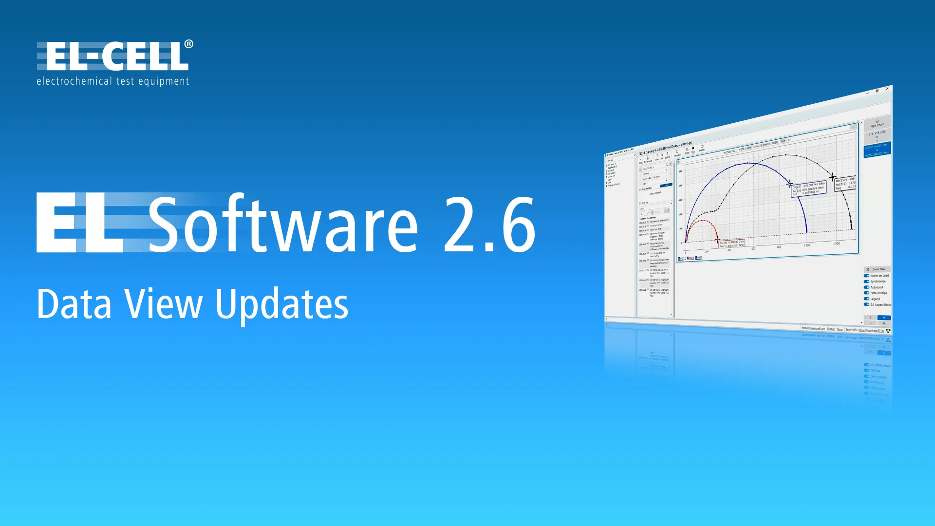
EL-Software: Data View Updates (Version 2.6, 10/2025)
In this Feature Spotlight video, we will discuss the new features of the updated Data View in EL-Software version 2.6.
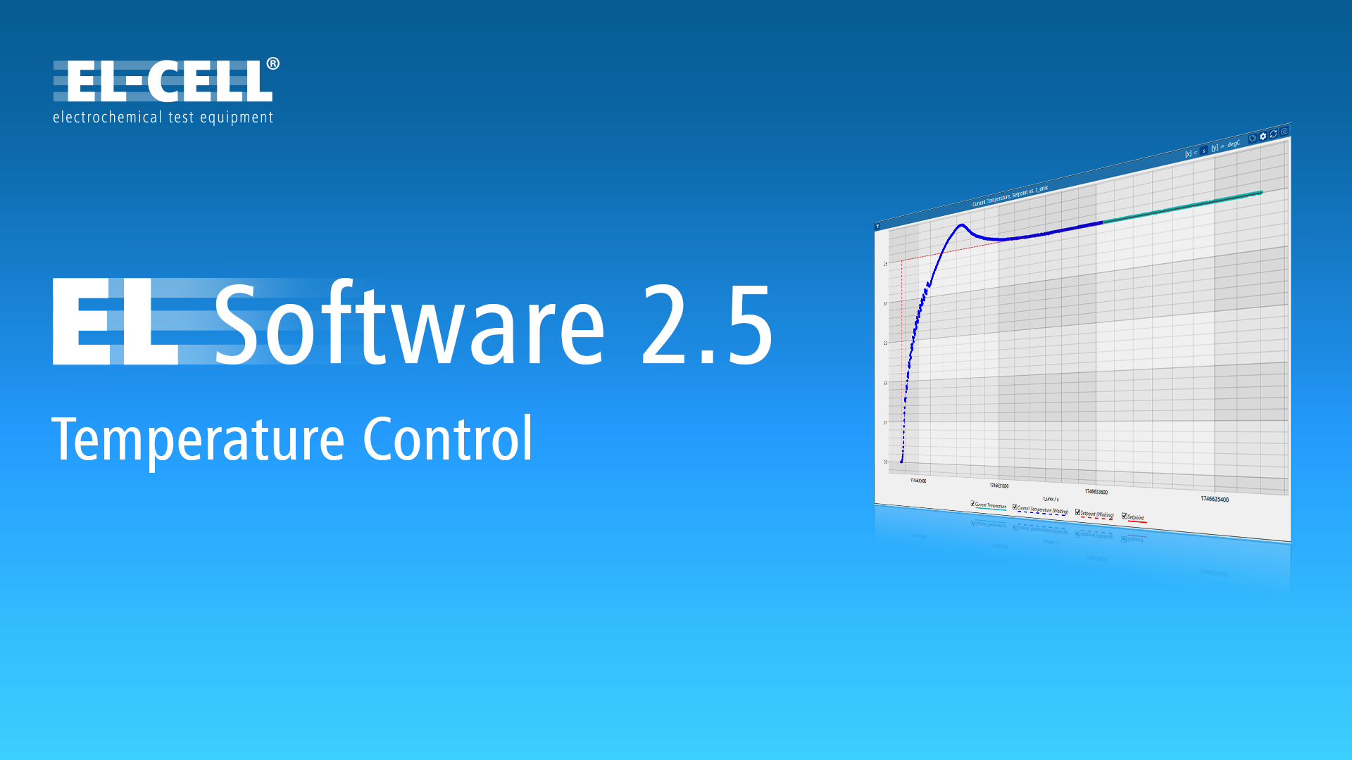
EL-Software Tutorial: Temperature Control (Version 2.5, 06/2025)
In this feature spotlight, you will learn how to define an initial temperature for each script of your experiment. You will also learn how to define dynamic temperatures in Lua scripts and get a basic idea of how to control the temperature of third-party temperature chambers within EL-Software.

EL-Software: Lua Functions in Charts (Version 2.4, 01/2025)
In this video, we will show you one of the new features of EL-Software Version 2.4: Lua Functions in Charts. This powerful feature allows you to apply mathematical functions directly to the plotted data, even while the measurement runs. It is a very flexible tool that can be used, for example, to display offsets or to combine different measurement categories.

EL-Software: Multi-Cell Views (Version 2.3, 10/2024)
In this video, we would like to introduce you to the new Multi-Cell view in EL-Software.
This new feature lets you quickly compare data from test cells or cell groups within your experiments. Evaluate your measurement data quickly and easily at any time without processing it with external tools.
A new Multi-Cell view is automatically generated when several test cells or cell groups use the same test protocol in your experiment. Of course, you can also use this powerful function to create custom comparisons using the data from all stored experiments.
PAT Series
PAT-Core Tutorial: Self-Assembly of the Reed Contact 2nd Gen. (07/2025)
In this video tutorial, we show how to insert the second-generation reed contact into the insulation sleeve of the PAT-Core.
This video is specifically made for situations where self-assembly is required. In most cases, prebuilt sleeves are used with the reed contact already fitted. The steps shown are also valid for insulation sleeves made of Peek.
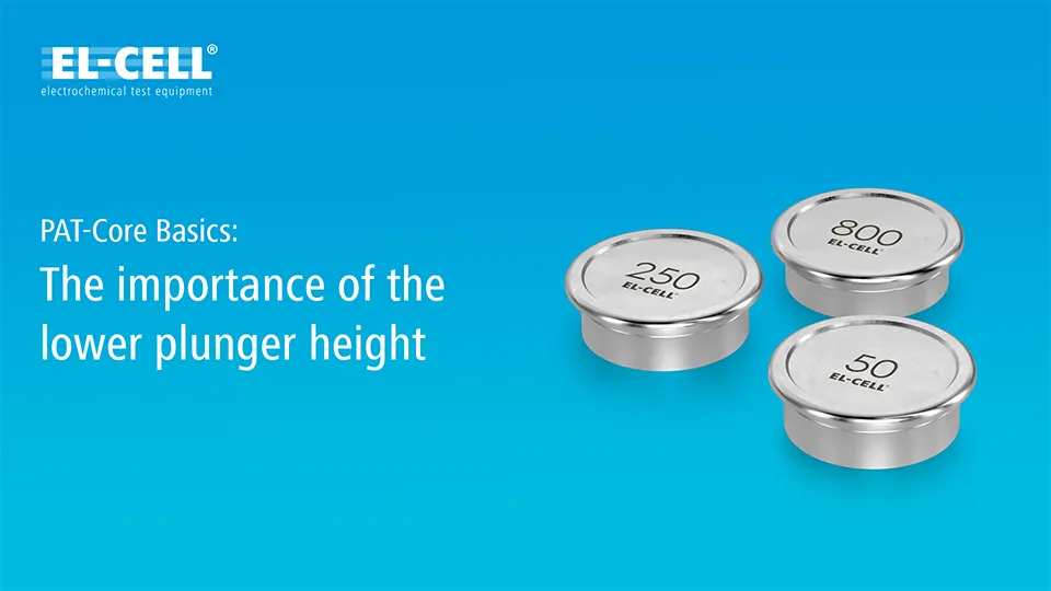
PAT-Core Basics: The lower plunger height (01/2021)
In this video, Dr. Matthias Hahn explains the importance of choosing the correct lower plunger height when measuring half-cell impedances with PAT-Cells.

Introduction PAT-Series Part 1: Overview
This video introduces the EL-CELL PAT series and shows the core features and benefits.

Introduction PAT-Series Part 2: The PAT-Core
Learn more about the funcionality and benefits of the PAT-Core, the essential part of every PAT-Cell, as well as assembly procedures.

Introduction PAT-Series Part 3: The PAT-Cell
Here we explain the different parts of the PAT-Cell and show how to replace them easily
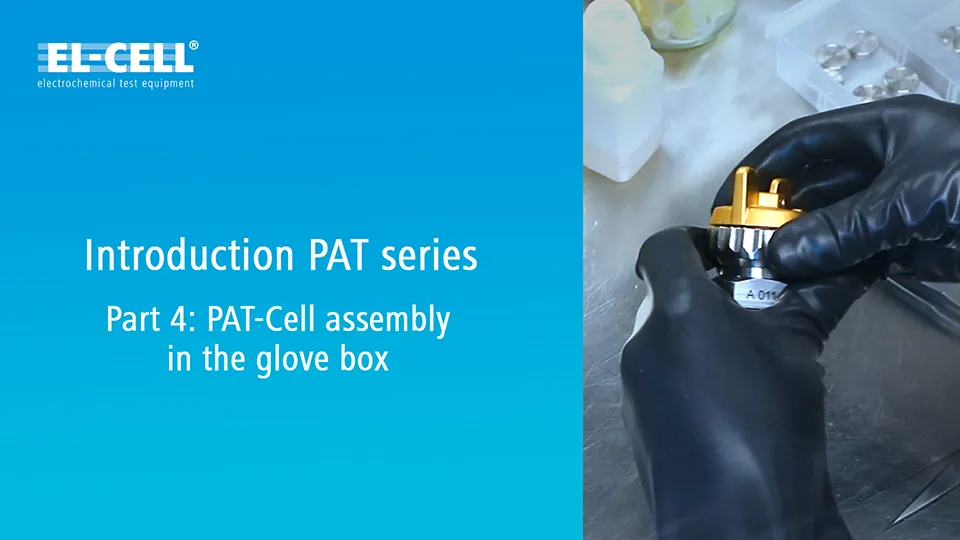
Introduction PAT-Series Part 4: PAT-Cell assembly in the glove box
See the assembly procedures of the PAT-Core and PAT-Cell in a glovebox environment.

How to assemble the PEEK insulation sleeves
In this video we will show you how to assemble the PEEK insulation sleeves in a few steps. In contrary to the preassembled single-use PAT-Core variants made of PP, the PEEK components need to be assembled before each use but have the advantage of reusability.
ECC-PAT-Core

Assembly of the ECC-PAT-Core
This video shows the components of the ECC-PAT-Core and assembly procedures.
ECC-Opto-Gas
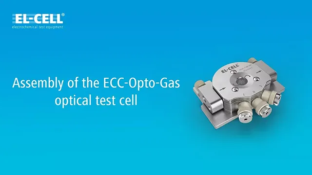
Assembly of the ECC-Opto-Gas optical test cell
Watch this video to learn how to assemble the ECC-Opto-Gas. This test cell specializes in the optical characterization of gas diffusion electrodes in metal-air batteries.
Dr. Matthias Hahn will guide you through all necessary steps, including pre-assembly and leak testing, cell filling and final assembly in the glove box environment.
ECC-Opto-10

ECC-Opto-10: Assembly procedures for side-by-side electrode setup (07/2022)
In this updated video, Dr. Matthias Hahn shows the required steps for assembling the test cell in the side-by-side electrode setup inside the glove box.

ECC-Opto-10: Assembly procedures for face to face electrode setup (10/2021)
Learn how to assemble the ECC-Opto-10 optical battery test cell in face-to-face electrode setup.
PAT-Cell-Opto-10
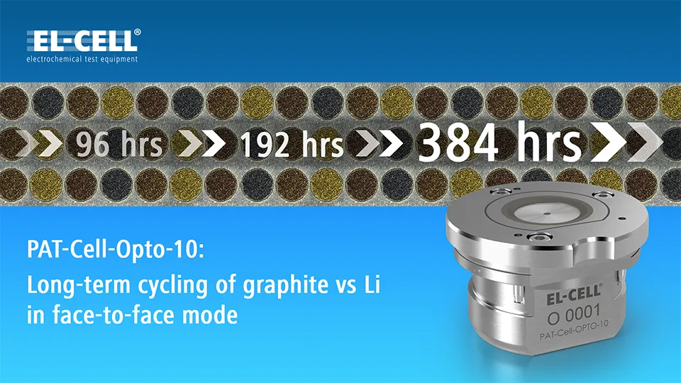
PAT-Cell-Opto-10: Long term cycling of graphite vs Li in face to face mode (09/2021)
In this video, Dr Matthias Hahn demonstrates the outstanding cycling stability and tightness of our new optical battery test cells.
For this purpose, we cycled graphite against lithium for approx. 400 hours (25 cycles) in a PAT-Cell-Opto-10. A PAT-Tester-x-8 was used as potentiostat while the data was evaluated in EL-Software.
As you can see from the curves shown, the die capacity retention of the test cell at the end of the experiment was still around 80% with a Coulomb efficiency of almost 100%.
The PAT-Cell-Opto-10 as well as the ECC-Opto-10 both have a new sealing concept with laser-welded glass metal feedthroughs and foil seals, which achieves far better results than conventional designs. This allows realistic visualisation of the processes within the battery, even during long-term operation.

PAT-Cell-Opto-10: Assembly procedures for side-by-side electrode setup (10/2022)
In this video, Dr. Matthias Hahn shows the required steps for assembling the test cell in the side-by-side electrode setup inside the glove box.
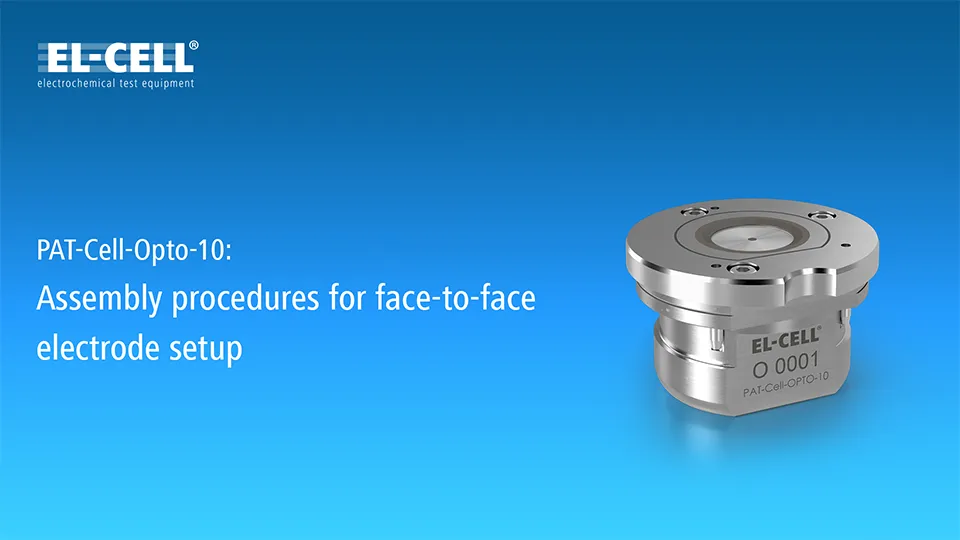
PAT-Cell-Opto-10: Assembly procedures for face-to-face electrode setup (10/2021)
Learn how to assemble the PAT-Cell-Opto-10 optical battery test cell in face-to-face electrode setup.
ECC-Opto-Std

ECC-Opto-Std Mode 3: Graphite electrode sandwiched with an LFP counter electrode
Using our ECC-Opto-Std test cell, we have placed a strip of a graphite electrode beside a piece of lithium foil having the shape of a semicircle. A glass fiber separator is pressed against this side-by-side assembly from below, so as to fill up the gap between the two electrodes. From below, a lithium iron phosphate (LFP) electrode is pressed against the separator serving as the counter electrode. The microscope “looks” through the sapphire window onto the graphite electrode with the active layer facing up, and the current-less lithium metal foil beside. For the electrochemical experiment, the graphite strip is connected to the working electrode of the potentiostat, the LFP semicircle to the counter electrode, and the lithium metal foil to the reference electrode. The video shows how the color gradient evolves along the width of the graphite electrode during lithiation/ delithiation.
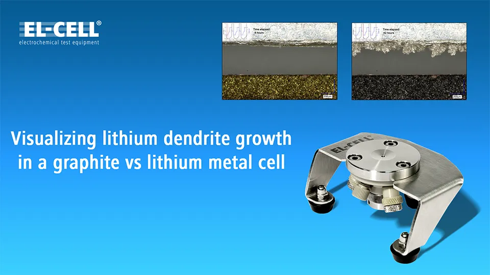
ECC-Opto-Std Mode 2: Visualizing lithium dendrite growth in a graphite vs lithium metal cell
Using our ECC-Opto-Std test cell, we have placed a strip of graphite next to a lithium metal electrode (having the shape of a semicircle) on top of a glass fiber separator soaked with electrolyte. A sapphire window is placed on top of the assembly. By means of the applied mechanical pressure, the soft glass fiber separator deliberately fills up the gap between the graphite strip and the lithium metal electrode. We call this a side-by-side arrangement, because the two electrodes are placed side-by-side rather than being sandwiched as in a conventional set-up.

ECC-Opto-Std Mode 1: Graphite electrode strip sandwiched with LFP Counter electrode
In this video, we show how the ECC-Opto-Std test cell can be used to visualize a potential gradient inside graphite, just by using a standard graphite electrode with a continuous copper foil as the current collector (rather than a holed current collector).

ECC-Opto-Std Standard sandwich mode: Free-standing graphite electrode on holed current collector
In this experiment, the ECC-Opto-Std test cell has been used to visualize the color change of a graphite electrode during electrochemical lithiation.
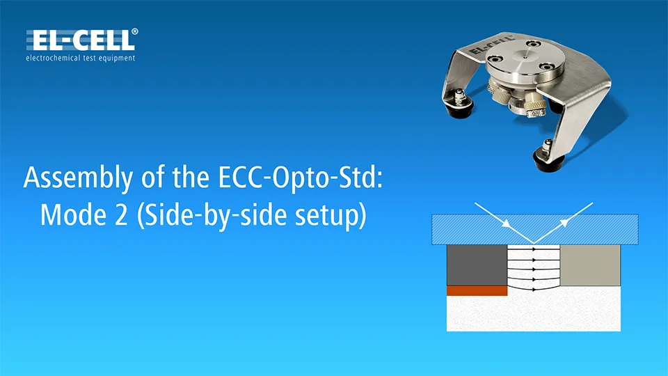
ECC-Opto-Std Assembly Mode 3 (3-electrode side-by-side setup)
In this video, we show how to build the ECC-Opto-Std test cell in the alternative assembly mode #3.
Again, a 1 mm wide electrode strip, cut from a conventional graphite electrode with copper foil current collector, is being used as the working electrode,and again this electrode strip is placed beside a piece of lithium metal foil.
However, this time the lithium metal is connected only to the reference electrode of the potentiostat, while a lithium iron phosphate electrode, placed below the graphite strip, is serving as the counter electrode.
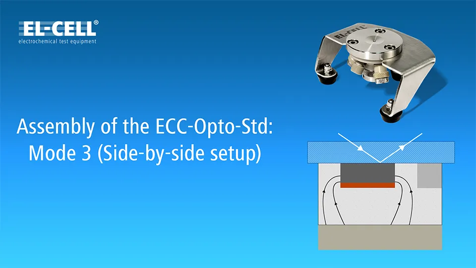
ECC-Opto-Std Assembly Mode 2 (2-electrode side-by-side setup)
In this video, we show how to build the ECC-Opto-Std test cell in the alternative assembly mode #2.
Again, a 1 mm wide electrode strip, cut from a conventional graphite electrode with copper foil current collector, is being used as the working electrode.
This time, the electrode strip is placed beside a lithium metal foil connected to both the counter and the reference electrode of the potentiostat.
With a microscope “looking” through the window, we can observe the color change of the graphite during charge and discharge
and, at the same time, the growth of dendrites at the lithium metal counter electrode.
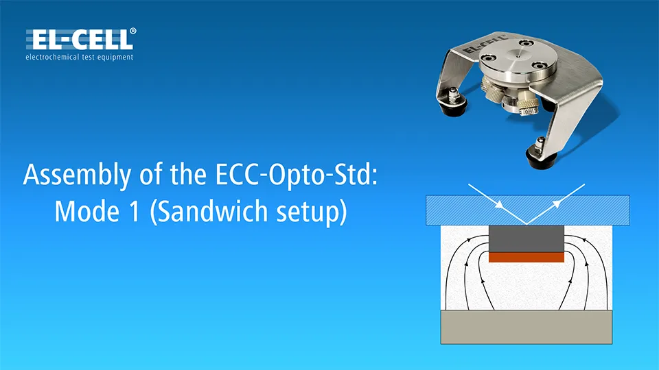
ECC-Opto-Std Assembly Mode 1 (2-electrode sandwich setup)
In this video, we show how to build the ECC-Opto-Std test cell in the alternative assembly mode #1.
A 1 mm wide electrode strip, cut from a conventional graphite electrode with copper foil current collector, is being used as the working electrode. This electrode strip is sandwiched with a lithium iron phosphate electrode connected to both the counter and the reference electrode of the potentiostat.
Importantly, the graphite layer is pointing towards the window on top, so that the current can only enter from the two edges of the graphite strip. This face-up geometry results in a gradient of the local electrode potential along the width of the electrode strip, rather than into the depth of the graphite layer.
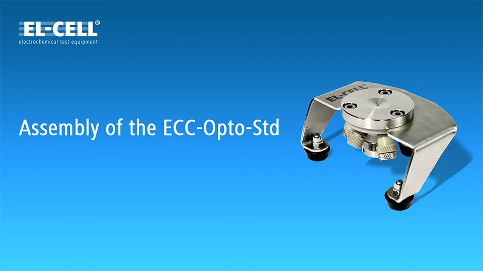
Assembly of the ECC-Opto-Std (Standard sandwich setup)
This video shows the general assembly of the test cell ECC-Opto-Std; a test cell for optical and X-ray characterization in the reflective mode.
EL-Cut

How to use the EL-Cut
ECC-StopRail

How to use the ECC-StopRail
ECC-CellLoad
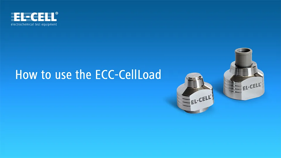
How to use the ECC-CellLoad
Any Comments about this Page?
Please leave us a note