Testing of Battery Materials with Mesh-type Reference Electrodes
A long time ago, we advertised to use a finger-type (aka wire-type) reference electrode.
Everything we wrote still holds. However, the bad news is that the finger-type reference electrode is no longer available. The good news is that we now have an even better solution: The mesh-type reference electrode.
The new mesh-type reference comes in two variants: fine and coarse. Both have the same web width of 50 µm and web thickness of 25 µm but different mesh sizes (see pictures below).
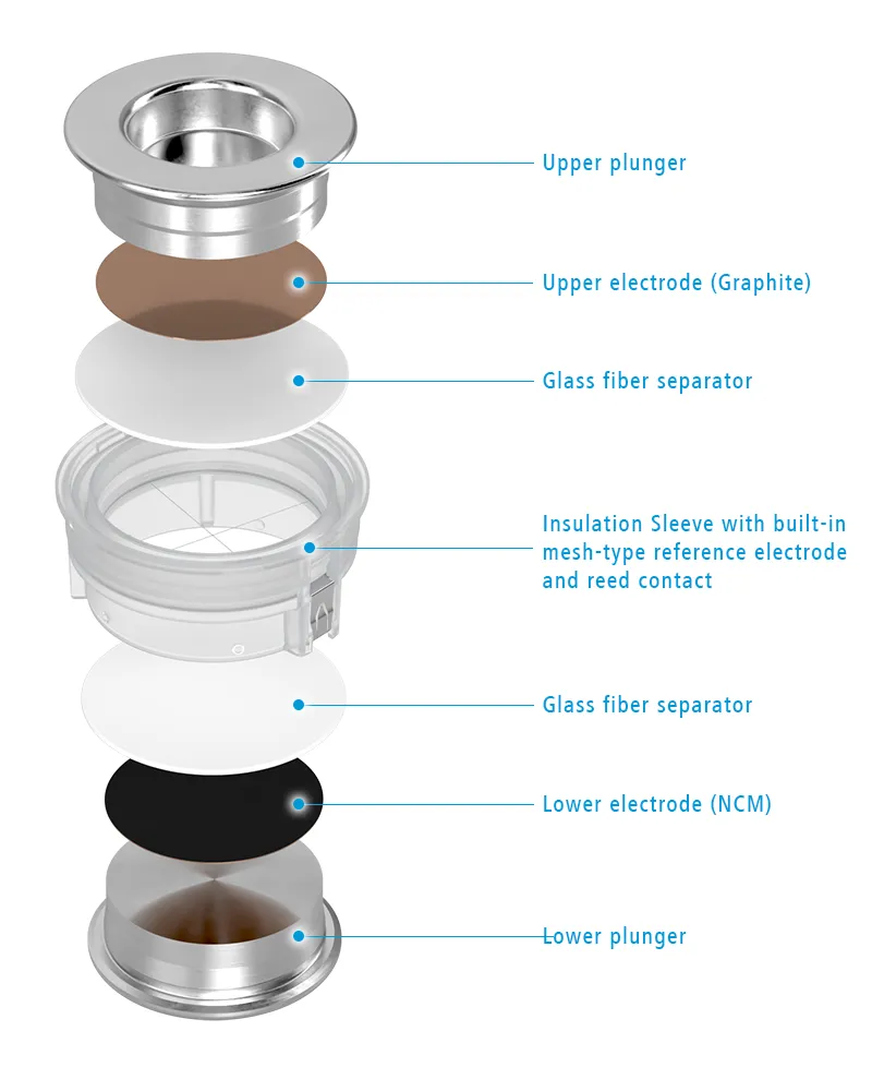
You will get the mesh ready assembled into our standard PP single-use sleeve. When assembling the cell, glass fiber separators are attached to the mesh, one on each side.
In both cases, the mesh is made of stainless steel. The mesh must first be coated with a suitable material to convert it into a reference electrode. How is this done?
One option is to coat the mesh with an active material such as LFP. A second possibility is to plate the mesh with lithium metal from one of the two sandwich electrodes in situ. The latter case is described below as an example.
Assembling the PAT-Core with the fine mesh-type reference electrode
The following is a brief description of the steps involved in assembling the PAT-Core cell stack that we are using here:
We have the hands in the glove box. In front of us is the sleeve with the mesh, with the narrower opening facing upwards. We place an 18 mm glass fiber separator, 260 µm thick, in the sleeve on the mesh, then an 18 mm NCM electrode, 100 µm thick. Then, we insert a size 250 lower plunger, turn the whole thing over, and insert it into the cell base of the PAT-Cell. We place a second glass fiber separator on top of the mesh, add 150 µl LP32 electrolyte, insert the graphite electrode, and finally, the upper plunger. Done.
The plating with a PAT-Tester-i-16 potentiostat
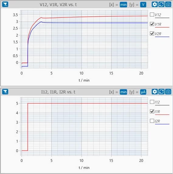
Next, we plug the cell into our PAT-Tester-i-16 and plate the mesh from the NCM electrode. The optimum conditions depend on the electrolyte selected. In our example, we tried it with 5 µA for one hour. This corresponds to 0.5% of the total lithium contained in the used NCM electrode.
The following diagrams plotted in EL-Software show the evolution of the voltages V1R and V2R during the initial 20 minutes of the one-hour plating process. Apparently, after about three minutes, the mesh’s potential stabilized.
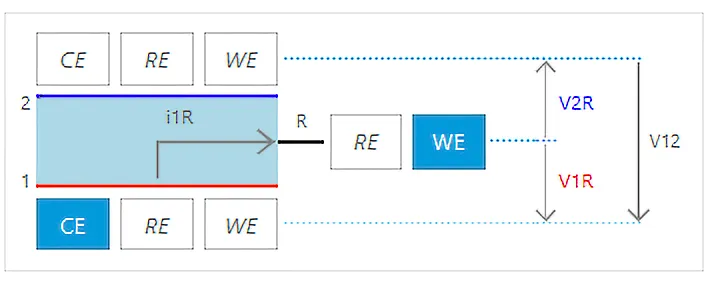
The corresponding connection matrix scheme for lithiating the mesh (R) from the NCM electrode (1):
Once the mesh is plated, the current can be applied to the full cell. The mesh now acts as a reference electrode to measure the potentials and impedances of the individual electrodes. Compared to a ring-shaped reference electrode, the typical measurement artifacts caused by inhomogeneous current density distribution are significantly reduced. This is the significant advantage of the mesh.
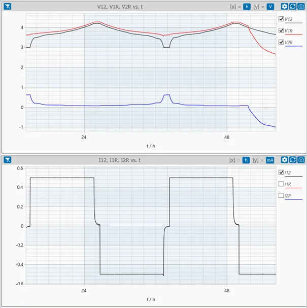
Unfortunately, there are also disadvantages. The biggest disadvantage is that the lithium metal deposited on the mesh is dendritic and does not adhere well to the stainless steel. The contact between the dendritic lithium metal and the stainless steel substrate was lost after approximately 50 hours; see diagrams below.
The good thing is that you can repeat the plating with a PAT-Tester, and this repetition can be automated using the test protocol.
Testing with the plated mesh reference
Diagrams showing two full cell cycles:
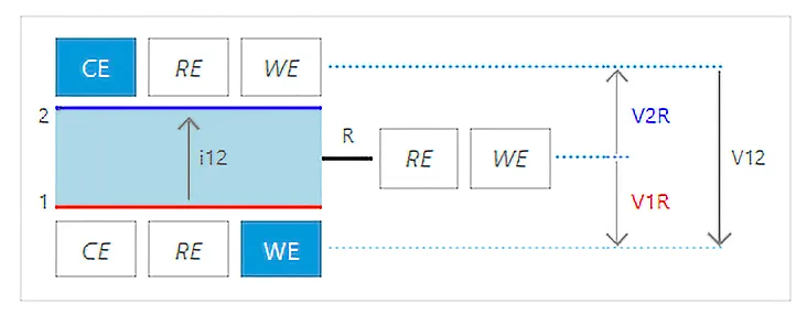
The corresponding connection scheme for cycling the full cell:
Conclusion
Try the mesh-type reference electrode to minimize the measurement artifacts from the standard ring-type reference’s non-perfect geometry. However, this mesh-type reference is not suited for long-term experiments.
Related products:
 Insulation sleeve (PP), stainless steel cross, no Separator, ECC1-00-0420-M/X
 Insulation sleeve (PP), stainless steel mesh, no Separator, ECC1-00-0210-N/X


Comments are closed.