Former test setup
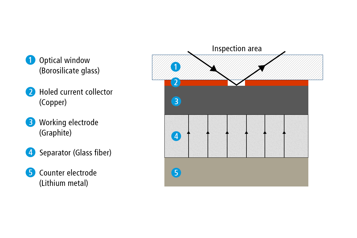
In a previous report, we have used the ECC-Opto-Std test cell to visualize the electrochemical lithiation of a free-standing graphite electrode sandwiched with a lithium metal counter electrode as the lithium source. Sketch 1a shows the sandwich geometry of the set-up used at that time. Notably, the graphite film was placed on a holed copper current collector. This way, the ions were allowed to move in the perpendicular direction between the two opposing electrodes, and an almost uniform color change was observed during the charge/discharge cycle. Actually, although invisible, this experiment involves an inevitable potential gradient along the depth of the graphite electrode, as was evidenced by the significant “phase shift” between cell voltage and color change.
Present test setup
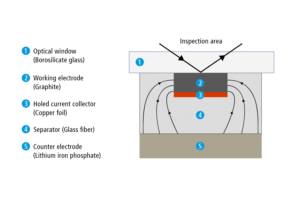
In the present report, we show how the ECC-Opto-Std test cell can be used to visualize a potential gradient inside graphite, just by using a standard graphite electrode with a continuous copper foil as the current collector (rather than a holed current collector). Sketch 1b depicts the set-up used for this experiment. A 9 mm diameter lithium iron phosphate (LFP) electrode was used as the lower electrode and lithium ion source. Two glass fiber discs (10 mm dia, 2 x 0.26 mm thick) were used as the separator. A 2 mm wide strip of the graphite electrode was placed on top of the separator, with the supporting copper current collector in between the LFP electrode and the graphite layer. This way, the copper foil blocks the direct perpendicular ion current between the two opposing electrodes, and forces the ions to enter the graphite at the two edges of the electrode strip. As a consequence, a beautiful color gradient can be observed along the plane of the graphite electrode.


Comments are closed.