ECC-Opto-Std
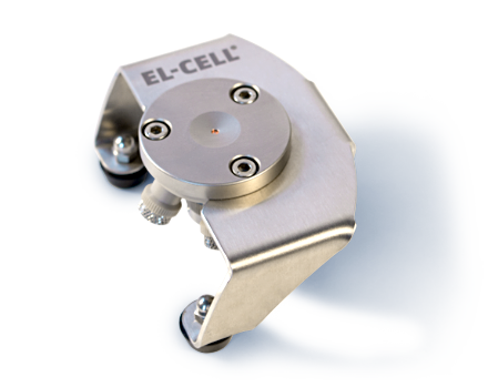
Test cell for optical and X-ray characterization in the reflective mode with face-to-face arrangement of electrodes
 Discover the ECC-Opto-10, our next generation optical test cell!
- High cycling stability due to improved sealing concept
- Improved cell design for easy handling
- Low profile design for use with light microscopes
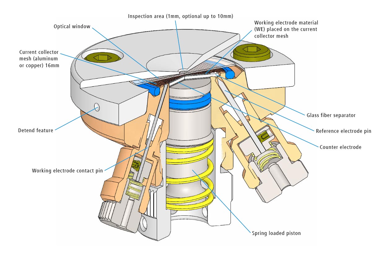

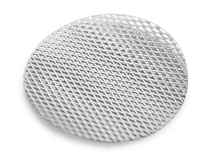
The ECC-Opto-Std test cell is dedicated to the inspection of electrodes by optical methods such as light microscopy or Raman spectroscopy working in the reflection mode. Basically, the respective instrument looks through a transparent window onto the backside of the working electrode. For this purpose the working electrode is to be supported on a perforated current collector or a current collector having a single small hole in its center. Different versions are available for use in either aprotic or aqueous electrolytes and can be adapted to the optical instrumentation used.
ECC-Opto-Std overview
Features
Adjustable, reproducible and homogeneous mechanical pressure on electrodes
Reliable low leakage sealing with PE washers and EPDM O-rings Easy and reliable electrolyte filling upon assembly Fast assembly and dismantling and easy cleaning of cell components Electrodes are easily accessible for post-mortem analysis Materials in media contact are stainless steel 1.4404 and PEEK (other materials on request)Specifications
| Height | 46 mm |
| Width | 88 mm |
| Depth | 63 mm |
| Weight | approx. 200 g |
| Electrode diameter | 10 mm |
| Electrolyte volume | min. 0.1 ml |
Application Notes
Attenuated total reflection Fourier transform infrared (ATR-FTIR) technique has become indispensable for surface-specific molecular analysis. At the Australian Synchrotron’s Infrared Microspectroscopy (IRM) beamline, we have advanced this technique by developing a novel piezo-controlled ATR-FTIR device designed for in-situ monitoring of electrochemical reactions in battery models. This piezo-controlled ATR-FTIR system incorporates high-precision piezoelectric linear translation stages, enabling sub-micron positioning and a gentle approach to engage samples with step intervals as small as 50 nm. By capturing high-quality spectral data during charge–discharge cycles of zinc ion batteries (ZIBs) at a controlled 100 nm distance from the electrode surface, the system overcomes common spectral artifacts associated with traditional reflectance setups and provides genuine interfacial chemical information without disrupting ongoing reactions. Combining the unique ability to monitor interfacial chemistry with its precision and reproducibility, this piezo-controlled ATR-FTIR device expands the analytical potential of synchrotron-FTIR microspectroscopy, offering transformative insights into the formation of solid electrolyte interphase and solvation mechanisms. The applications in ZIBs demonstrated in this study highlight the capability of the piezo-controlled ATR-FTIR technique for understanding critical interfacial processes that underpin energy storage performance and catalysis research, setting a new standard for synchrotron-FTIR studies of dynamic interfacial phenomena.
Read the articleManual
 | ECC-Opto-Std User Manual | |
| Release | 2.97 | |
| Release Date | January 2026 | |
| Type | ||
| Size | 2 MB | |
| Download |
Delivery scope

Consumables
Spare parts
Test cell

Frequently asked questions
Can I use the provided borosilicate glass window with any lithium battery electrodes?
Borosilicate glass is a good choice for all common cathode materials and also lithium titanate as the working electrode. However, some anode material such as lithium metal and lithiated graphite may react with the glass window forming greyish spots of elemental silicon on the glass surface. We therefore recommend using sapphire (Al2O3) windows with anode materials.
What is the difference between the ECC-Opto-Std and ECC-Opto-Aqu?
The basic difference is that for the ECC-Opto-AQU gold and PEEK are used for the parts coming into contact with the electrolyte. Gold is stable in most aqueous electrolytes (an important exception are solutions containing chloride), but is sometimes not stable in aprotic electrolytes (gold may form alloys with Li when used as a current collector for the negative electrode in Li+ containing solutions). We have also seen gold corroding in aprotic surpercapacitor electrolytes, R4NBF4 in MeCN, when used as the positive current collector.
Please note that the PEEK polymer used in both cells for the cell body has some stability limits. PEEK is not recommended for aqueous H2SO4 at concentrations >50% (as PEEK is getting sulfonated) and concentrated HNO3. In general, using one and the same cell for both aqueous and aprotic electrolytes may cause trouble because of cross contamination, especially from the aqueous towards the aprotic systems.


Accessories
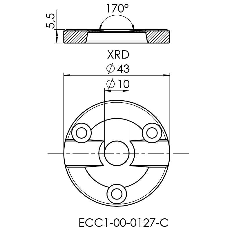
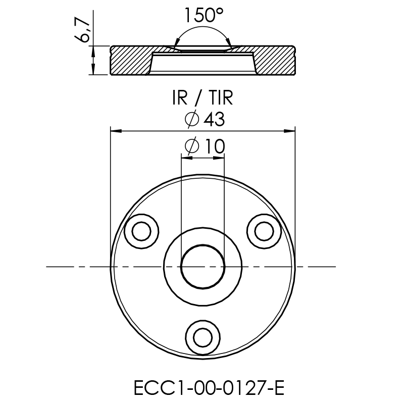
Window kits
Optional window kits
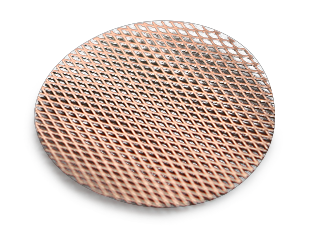
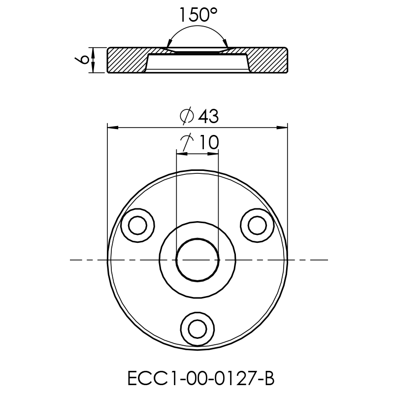
As a standard, the ECC-Opto-Std is equipped with a borosilicate glass window1 (Order no. LAB0018/V) and a cell lid with a 2 mm diameter window opening (Order no. ECC1-00-0127-A).
Depending on your testing purposes additional window kits are available. Each kit includes one or more windows and a modified cell lid. Further window materials like magnesium oxide, silicon dioxide, silicon nitride or PET (Mylar®) are available on request.
2 We strongly recommend placing a thin polyimide foil between the window and the electrode to prevent chemical reactions of the beryllium.
Cell holder
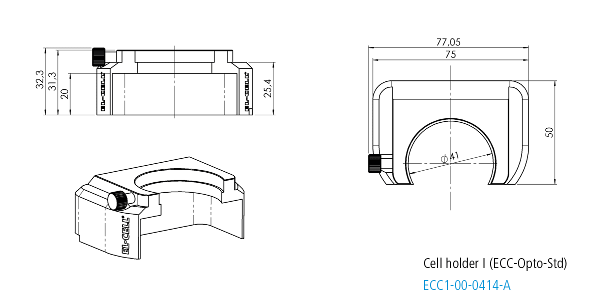
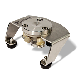
Cell holder I for ECC-Opto-Std
The Cell holder I is designed for the use of the ECC-Opto-Std in light microscopes. It fits nicely on sample stages of most manufacturers (e.g. Thermofisher or Renishaw) utilizing standard microscope slides (75 x 26 mm, ISO 8037-1).
Specifications

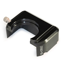
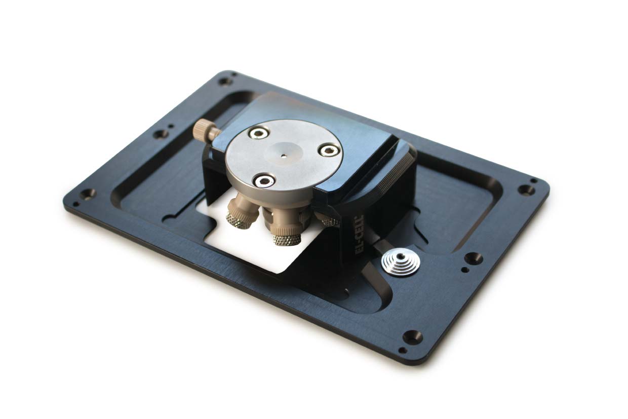
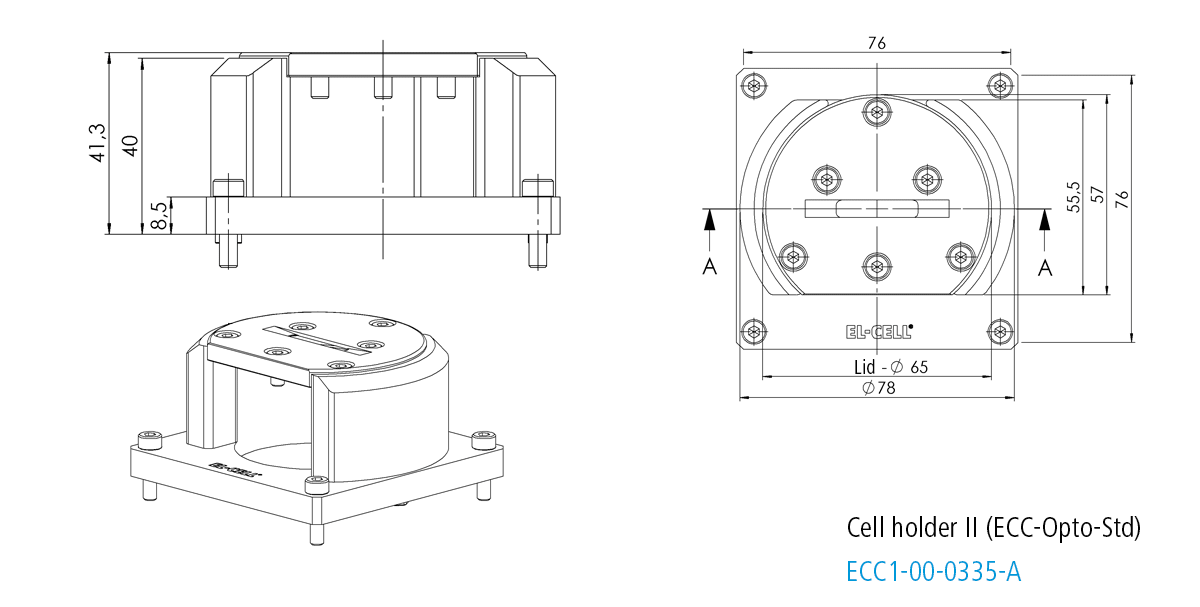
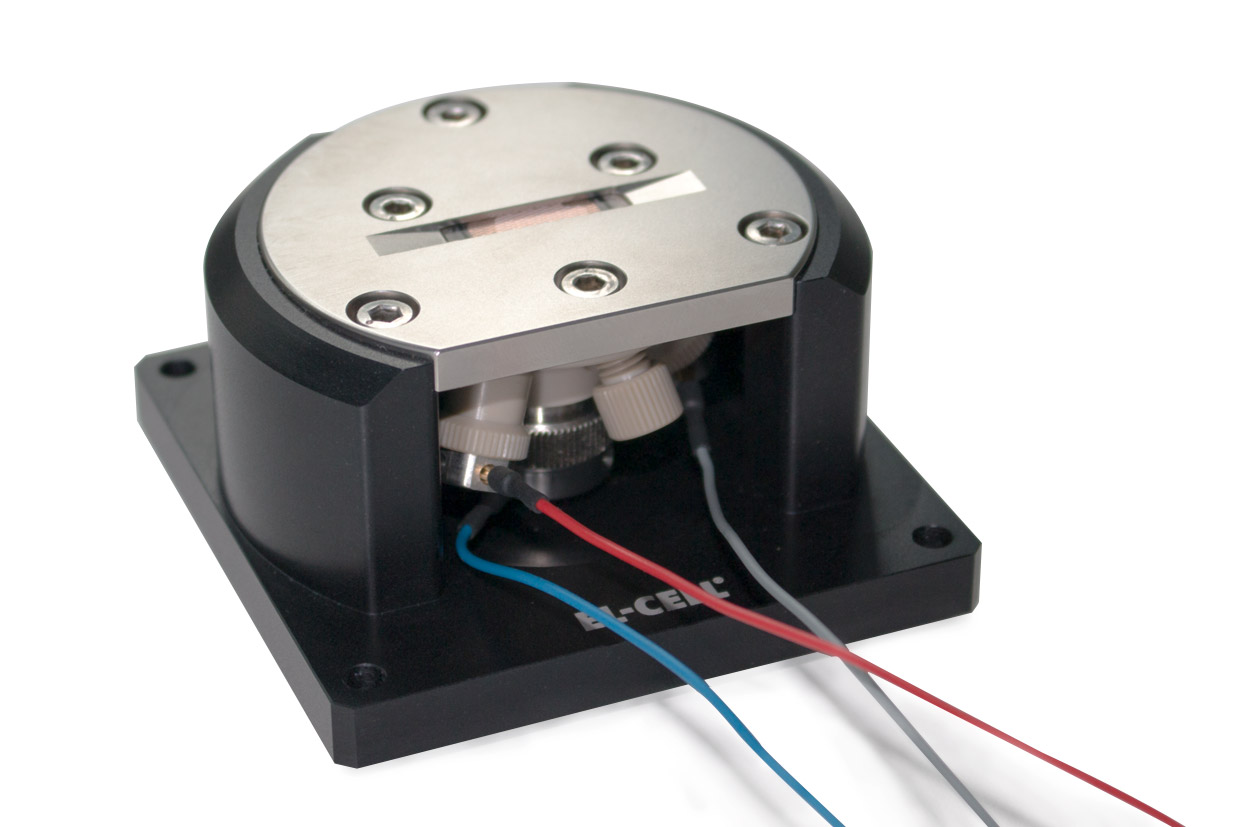
Cell holder II for ECC-Opto-Std
The Cell holder II is designed for the use of the ECC-Opto-Std in XRD microscopes like the Bruker D8.
Specifications

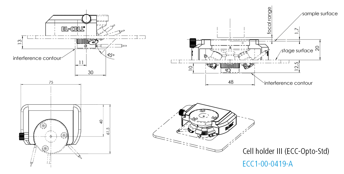
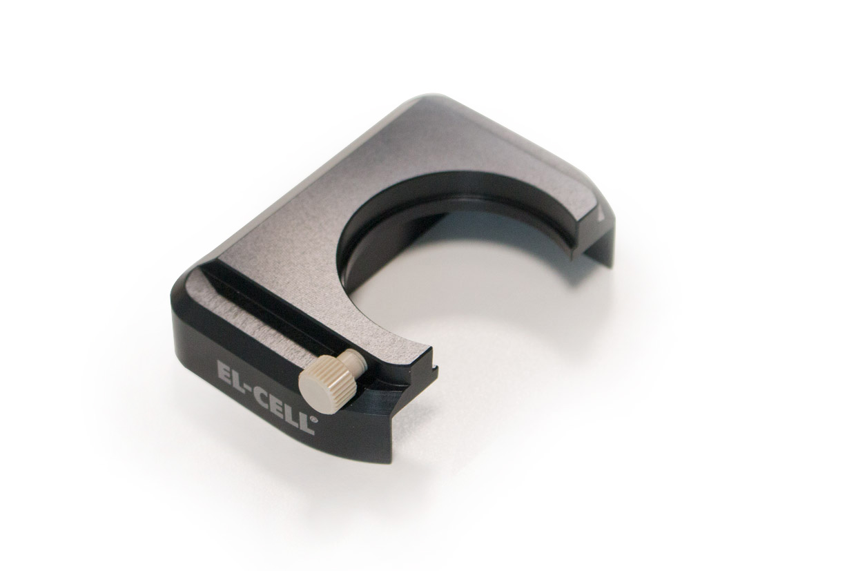
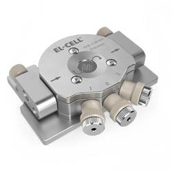
Cell holder III for ECC-Opto-Std
The Cell holder III is designed for the use of the ECC-Opto-Std in a Bruker FTIR Hyperion 2000 microscope.
Specifications

Gallery
-
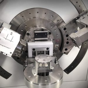

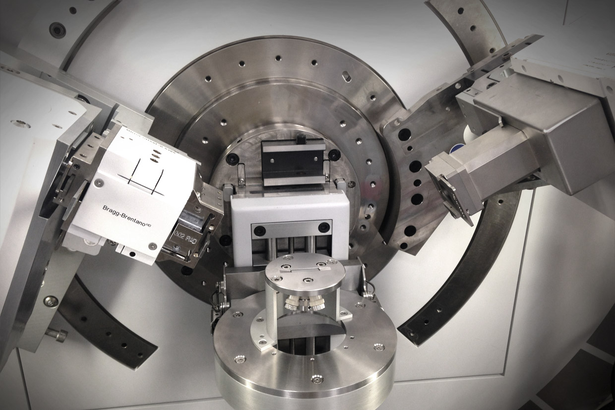
- The ECC-Opto-Std with ECC-Opto Beryllium window kit II has been installed in the Empyrean diffractometer from Malvern Panalytical for CC cycling experiments.
-
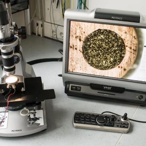
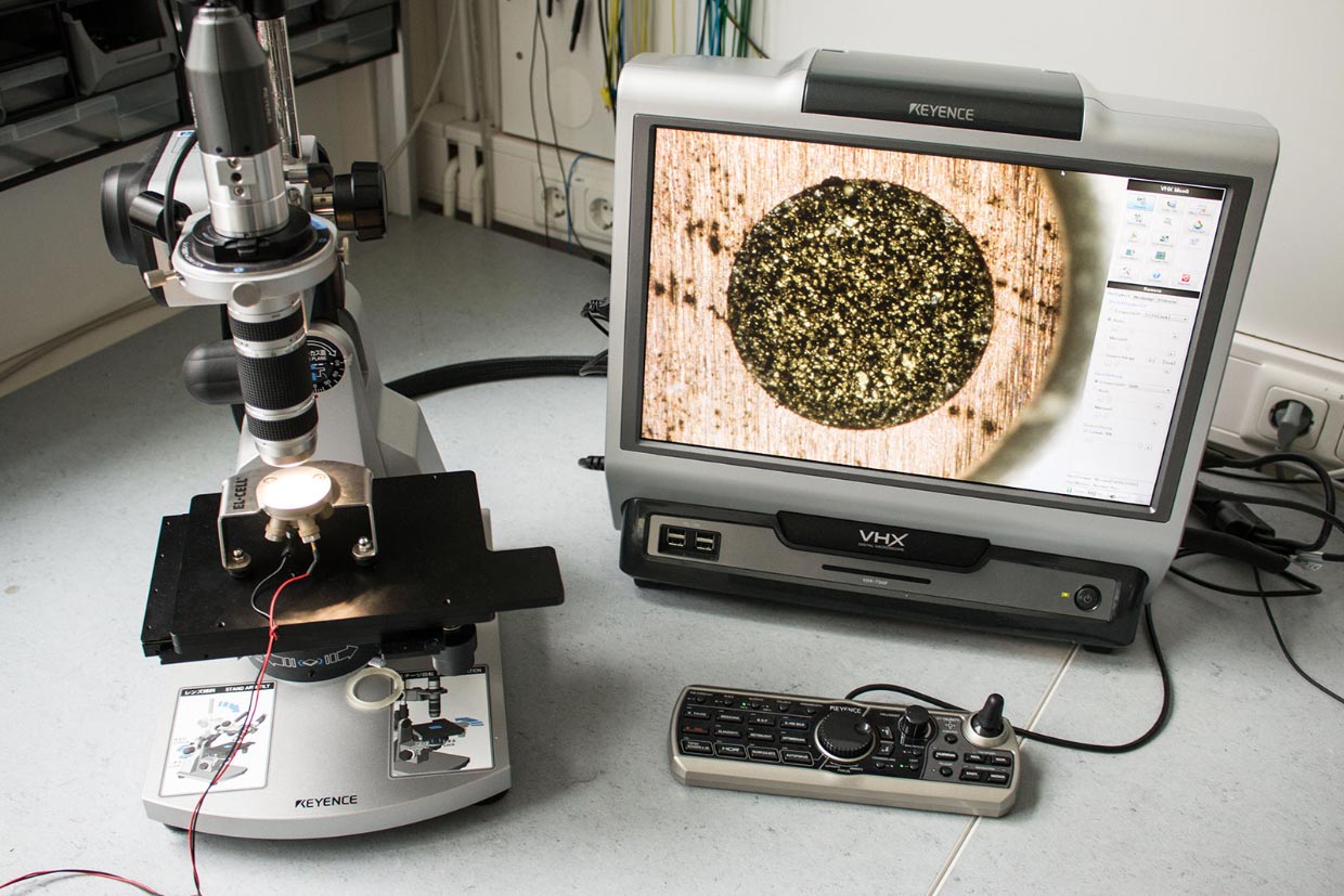
- Test setup with ECC-Opto-Std and Keyence VHX-700FD microscope
-
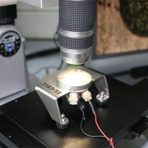
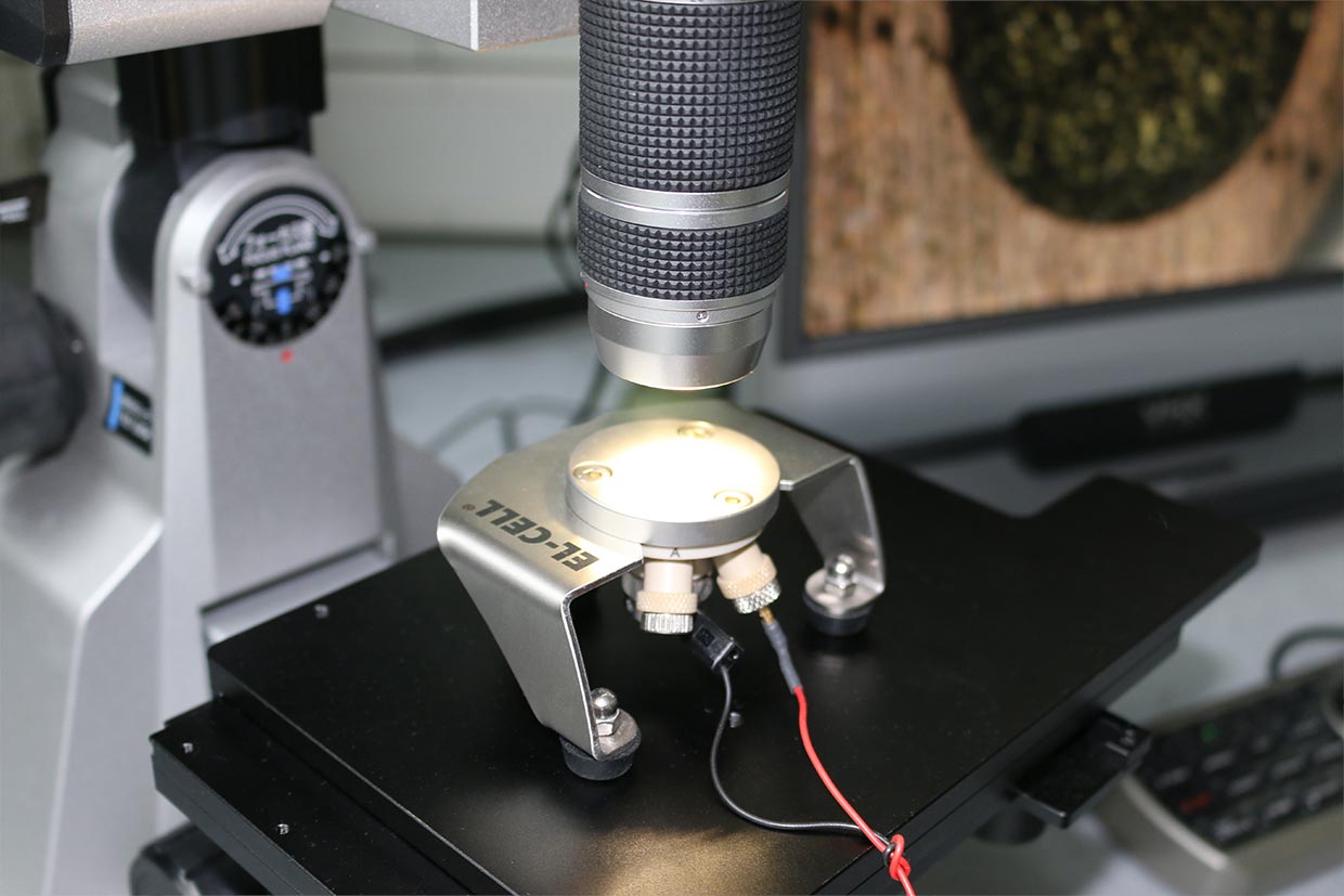
- ECC-Opto-Std test setup
-
- Dendrite growth during electrochemical lithiation visualized using a ECC-Opto-Std test cell.
-
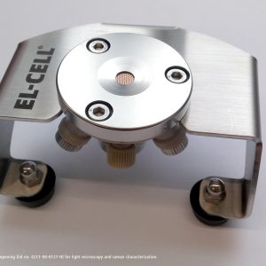
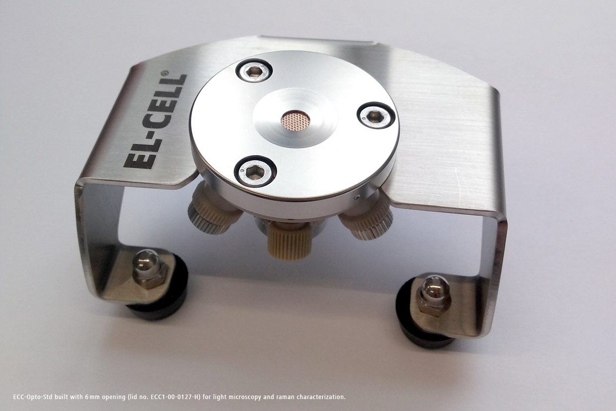
- ECC-Opto-Std with 6mm opening
Videos
ECC-Opto-Std Assembly Mode 1 (2-electrode sandwich setup) 04/2018
In this video, we show how to build the ECC-Opto-Std test cell in the alternative assembly mode #1.
A 1 mm wide electrode strip, cut from a conventional graphite electrode with copper foil current collector, is being used as the working electrode. This electrode strip is sandwiched with a lithium iron phosphate electrode connected to both the counter and the reference electrode of the potentiostat.
Importantly, the graphite layer is pointing towards the window on top, so that the current can only enter from the two edges of the graphite strip. This face-up geometry results in a gradient of the local electrode potential along the width of the electrode strip, rather than into the depth of the graphite layer.
ECC-Opto-Std Assembly Mode 2 (2-electrode side-by-side setup) 04/2018
In this video, we show how to build the ECC-Opto-Std test cell in the alternative assembly mode #2.
Again, a 1 mm wide electrode strip, cut from a conventional graphite electrode with copper foil current collector, is being used as the working electrode.
This time, the electrode strip is placed beside a lithium metal foil connected to both the counter and the reference electrode of the potentiostat.
With a microscope “looking” through the window, we can observe the color change of the graphite during charge and discharge
and, at the same time, the growth of dendrites at the lithium metal counter electrode.
ECC-Opto-Std Assembly Mode 3 (3-electrode side-by-side setup) 04/2018
In this video, we show how to build the ECC-Opto-Std test cell in the alternative assembly mode #3.
Again, a 1 mm wide electrode strip, cut from a conventional graphite electrode with copper foil current collector, is being used as the working electrode,and again this electrode strip is placed beside a piece of lithium metal foil.
However, this time the lithium metal is connected only to the reference electrode of the potentiostat, while a lithium iron phosphate electrode, placed below the graphite strip, is serving as the counter electrode.
ECC-Opto-Std Assembly (Standard sandwich setup) 07/2015
This video shows the general assembly of the test cell ECC-Opto-Std; a test cell for optical and X-ray characterization in the reflective mode.
ECC-Opto-Std Standard sandwich mode: Free-standing graphite electrode on holed current collector 05/2016
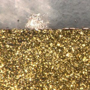
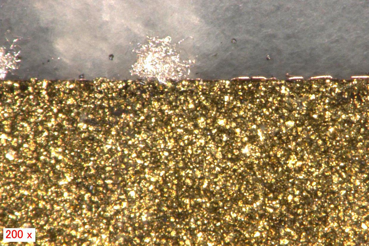
In this experiment, the ECC-Opto-Std test cell has been used to visualize the color change of a graphite electrode during electrochemical lithiation. A 10 mm diameter free-standing graphite electrode was used as the working electrode (WE). The WE was sandwiched with a glass fiber separator and a lithium metal counter electrode. A holed copper foil was used as the WE current collector. The microscope “looked” through the 1 mm diameter hole in the copper foil onto the backside of the graphite electrode. One picture was taken every 5 minutes.
The time-lapse video starts at the fully lithiated state after the graphite electrode had been fully discharged overnight to 5 mV versus the lithium metal counter electrode. The next 2.5 cycles are shown, starting with the golden color of the fully lithiated graphite, and ending up with the silver-black color of almost pure graphite. Both charge and discharge were conducted at constant current with a rate of C/3, followed by constant voltage periods till the current had dropped to C/30.
ECC-Opto-Std Mode 1: Graphite electrode strip sandwiched with LFP Counter electrode 07/2017
In this video, we show how the ECC-Opto-Std test cell can be used to visualize a potential gradient inside graphite, just by using a standard graphite electrode with a continuous copper foil as the current collector (rather than a holed current collector).
A 9 mm diameter lithium iron phosphate (LFP) electrode was used as the lower electrode and lithium ion source. Two glass fiber discs (10 mm dia, 2 x 0.26 mm thick) were used as the separator. A 2 mm wide strip of the graphite electrode was placed on top of the separator, with the supporting copper current collector in between the LFP electrode and the graphite layer.
This way, the copper foil blocks the direct perpendicular ion current between the two opposing electrodes, and forces the ions to enter the graphite at the two edges of the electrode strip.
As a consequence, a beautiful color gradient can be observed along the plane of the graphite electrode.
Read more about this sample test
ECC-Opto-Std Mode 2: Visualizing lithium dendrite growth in a graphite vs lithium metal cell 10/2017
Using our ECC-Opto-Std test cell, we have placed a strip of graphite next to a lithium metal electrode (having the shape of a semicircle) on top of a glass fiber separator soaked with electrolyte. A sapphire window is placed on top of the assembly. By means of the applied mechanical pressure, the soft glass fiber separator deliberately fills up the gap between the graphite strip and the lithium metal electrode. We call this a side-by-side arrangement, because the two electrodes are placed side-by-side rather than being sandwiched as in a conventional set-up.
For the electrochemical cycle, the graphite strip is connected to the working electrode of the potentiostat, the lithium metal semicircle to the counter and reference electrode. The video shows how the color gradient evolves along the width of the graphite electrode during lithiation/ delithiation, and how lithium metal dendrites grow and shrink at the edge of the lithium metal counter electrode.
Noteworthy, many dendrites grown during the plating half cycle survive the subsequent stripping half cycle. We stopped the video just before this irreversibility resulted into an internal short circuit.
Read more about this sample test
ECC-Opto-Std Mode 3: Graphite electrode sandwiched with an LFP counter electrode 12/2017
Using our ECC-Opto-Std test cell, we have placed a strip of a graphite electrode beside a piece of lithium foil having the shape of a semicircle. A glass fiber separator is pressed against this side-by-side assembly from below, so as to fill up the gap between the two electrodes. From below, a lithium iron phosphate (LFP) electrode is pressed against the separator serving as the counter electrode. The microscope “looks” through the sapphire window onto the graphite electrode with the active layer facing up, and the current-less lithium metal foil beside. For the electrochemical experiment, the graphite strip is connected to the working electrode of the potentiostat, the LFP semicircle to the counter electrode, and the lithium metal foil to the reference electrode. The video shows how the color gradient evolves along the width of the graphite electrode during lithiation/ delithiation.
Read more about this sample test
Recommended tools
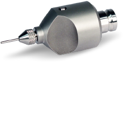
ECC-LiPunch
Punching tool for lithium foil. The recommended size for use with the ECC-Opto-Std is 10 mm.
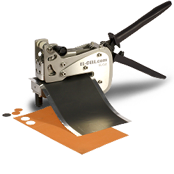
EL-Cut
High Precision Cutting Tool eliminates torn and chipped electrode edges. The recommended size for use with the ECC-Opto-Std is 10 mm.
Related products
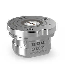
PAT-Cell-Opto-10
Advanced test cell for optical characterization in the reflective mode utilizing the PAT socket.
ECC-Opto-Std-Aqu
Test cell for optical characterization in the reflective mode with face-to-face arrangement of electrodes. For aqueous electrochemistry.
ECC-Opto-Gas
Test cell for optical characterization of gas diffusion electrodes in metal-air batteries.