Testing materials for lithium-ion batteries
A battery is a can with two terminals named plus and minus, or 1 and 2. Testing this battery means that you apply either a voltage (V12) profile or a current (i12) profile across the two terminals, and measure the corresponding current or voltage response. The profile can have many different shapes such as square, triangle, sine, or some arbitrary profile. This concept applies to small and large battery cells as well as to arrays of such battery cells connected in series and/or in parallel (battery modules or packs). One could therefore think that a single battery tester is good for all those configurations. This is not true. Battery testers for R+D on battery materials must fulfill very special requirements as we will discuss in the following.
Our focus here is on R+D battery testers that are specialized on battery experiments carried out to understand and improve the chemical ingredients of the battery: anode, cathode and electrolyte. For simplicity, we only consider today’s most prominent battery chemistry comprised of a lithium metal oxide as the cathode material (such as NCM) and graphite as the anode material. Both are layered materials, which can accommodate lithium ions between their layers. In the battery, the two electrodes are sandwiched with a separator in between them. The porous electrodes and separator are soaked with an electrolyte solution containing lithium cations and PF6 anions in a mixture of organic solvents. Initially, the NCM lattice is filled up with lithium ions, while the graphite lattice is empty. This is the energetically favored (lowest overall energy) configuration. The lithium ions feel good in the NCM and see no reason to leave to the opposite graphite electrode. Electrically speaking, the voltage of the battery is zero. Charging the battery means to force lithium ions from 1 (NCM) to 2 (graphite) through the electrolyte layer, and at the same time move the same number of electrons through the outside part of the circuit, again from 1 to 2. We say “charging”, but this verb is misleading. In fact, we don’t end up with any excess charge on the electrodes, but instead just convert electric into chemical energy. Charge separation is only at an atomic scale inside the electrode materials. The device we use to charge or discharge (to cycle) the battery is the battery tester.
By applying a current between the two electrodes, we move electrons from the NCM to the graphite backbone along the outside part of the circuit and, at the same time along the inner part of the circuit, extract the same number of lithium ions from the NCM lattice and move them through the separator into the graphite lattice. In the fully charged state, at 4.2 V cell voltage, all “easily” available Li ions from the NCM lattice have been brought over to the graphite lattice. And during discharge, those Li ions will then migrate back into the NCM lattice.
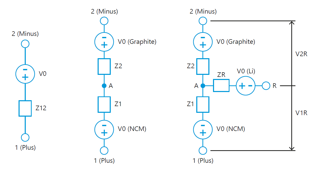
Equivalent circuits are often used to model what goes on in a battery and are helpful for a basic understanding. The simplest circuit (Fig. 1a) is just a resistance-less voltage source V0 in series with a resistance (or more precisely impedance) Z12. Both V12 and Z12 depend on the SOC of the battery cell, and can be determined empirically.
A better model takes into account that the battery cell is actually made up of two electrodes in series (Fig. 1b). Now each electrode (“half cell”) is represented by its respective voltage source and impedance. This model accounts for the capacitance matching of the two electrodes: At best, the graphite electrode can accommodate all the Li ions released from the NCM during charge, no more, no less. Also, this model accounts for the fact that the electrodes can have very different kinetics, i.e. impedance, for the uptake and release of Li ions, again dependent on their SOC.
How can we find out about the individual characteristics of the two half cells?
This is actually the question that lets us understand the special requirements of the R+D battery tester.
From left to right:
Fig. 1a: Equivalent circuit for a battery represented by an ideal voltage source V0 and impedance Z12. Both V0 and Z12 depend on the state of charge.
Fig. 1b: Two-electrode equivalent circuit showing the two electrodes NCM (1) and graphite (2). Both electrodes are described by their chemistry specific dependence of voltage and impedance on the respective SOC. We would like to know the voltages relative to point A, V1A and V2A.
Fig. 1c: Three-electrode equivalent circuit including the lithium metal reference electrode (R). Details see text.
The above two-electrode equivalent circuit (Fig. 1b) promises we could directly measure the two half cell voltages by connecting a voltmeter between the respective battery terminal and the node A. However, node A is located inside the electrolyte and so we can’t directly connect the LO test probe of our voltmeter to this point. Instead, we place here a third, so called reference electrode, for instance a lithium metal ring placed at the edge of the separator. With this 3-electrode set-up, the two half cell voltages can now be easily measured, albeit with an unknown voltage offset V0(R) which is defined by the nature/chemistry of the given reference electrode. The half cell voltages V1R and V2R can be easily measured; they are often named electrode potentials, and must be referred to the chemistry used as the reference. In our example, the reference electrode is lithium metal and accordingly V1R and V2R are given in units of “V vs. Li/Li+”. As long as R is only used as a measuring probe, with zero current across ZR, the voltage offset V0(R) is constant during the experiment.
What can we do better with a battery that has 3 rather than 2 electrodes?
Well, we can now measure three rather than only one voltage. And we can control one out of these three voltages in potentiostatic test mode. In galvanostatic mode, we can direct the charge flow between electrode 1 and 2 (most common), or between R and 1, or between R and 2. We come back to these “strange” modes later on.
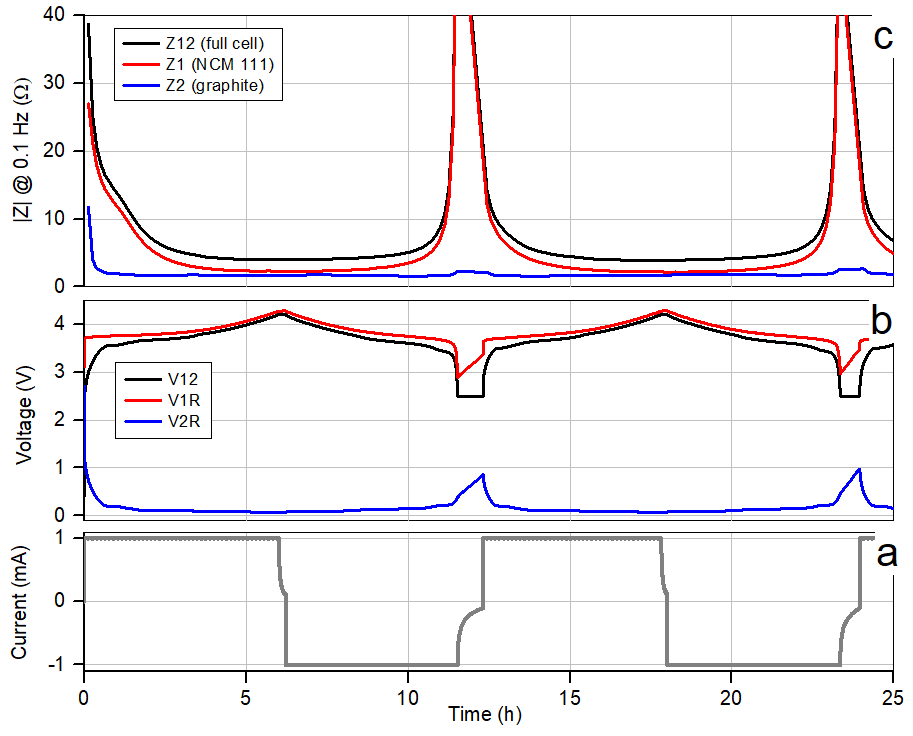
For now, we focus on the results of a basic 3-electrode experiment the results of which are depicted in the graphs below (Fig. 2). The test cell used here comprises an NCM|graphite sandwich with a lithium metal ring located at the edge of the in-between separator. We charge the cell with a constant current i12 till the cell voltage V12 reaches 4.2 V, hold the voltage for a while, then discharge back to the initial voltage of 2.5 V. With a 2-electrode battery tester, one would only see the black V12 voltage trace during the cycle. No chance to tell apart what happens at the different electrodes. It is only thanks to the reference electrode, that we can distinguish between the individual electrode potentials, red line for NCM, blue line for graphite.
Same for the impedance. The modulation of the DC current by a sinusoidal excitation leads to a modulation of the cell voltage V12 and so of the two electrode potentials V1R and V2R. The ratio between the amplitudes of voltage and current, the impedance Z, is a measure of how easy charge carriers can move at a given frequency. And again, only with the reference electrode, we can distinguish between cathode (Z1) and anode (Z2).
Fig. 2: Test results obtained with a PAT-Tester-i-16 and a 3-electrode PAT-Cell. For details see text.
For the experiment shown in Fig. 2, impedance at 0.1Hz was measured intermittently every few minutes. With this special technique all important dc and ac parameters of the battery and the individual electrodes are obtained in one single experiment.
What are the two “strange” galvanostatic modes of the R+D battery tester good for? Ideally, one electrode is the source, the other one is the sink for lithium ions, and there is no other interaction between them. In reality, the electrodes interact with each other. For example, manganese ions can be leached out from the NCM lattice in a side reaction and poison the graphite electrode. To understand how the graphite electrode would age during cycling without this side reaction, one can build a symmetric graphite (1)|graphite (2) cell with a lithium metal ring electrode (R). Then apply a current i1R to lithiate graphite (1) from the lithium ring (R). And finally run a conventional cycle test with i12 control to shuttle the lithium ions back and forth between the two graphite electrodes. To name just one of many new possibilities with a 3-electrode cell.
From the above test cases, we can compile the specific requirements for an R+D battery tester as follows.
- The battery tester needs to support 3-electrode cells. That is, the tester needs at least 3 leads. These leads are typically labeled working, counter and reference electrode (WE, CE and RE) rather than plus and minus. And often two additional leads are provided named WE-Sense and CE Sense.
- The tester must be capable to record both half cell voltages simultaneously. It is not enough to record just the voltage under control.
- 3-electrode test cells are small and tests are only on single cells. Thus, the requirements on the maximum current and voltage are modest, say 100 mA and 5V. Importantly, the voltage range must be bipolar, at least +/-5V, in order to support the different reference electrodes. Many battery testers only have a unipolar voltage range.
- High accuracy and resolution for both current and voltage are needed for precise determination of Coulomb (cycle) efficiency. Latest technology works with 24 bit ADCs and 18 bit DACs and on-going calibration against built-in standards. Here the limits are defined by the test cell and not by the electronics.
- To switch between the different potentiostatic and galvanostatic control modes, the user normally has to change the wiring between the tester channel and the test cell. Much more comfortable is a software-controlled switchover like the Connection Matrix of the PAT-Tester series.
- Indispensable test techniques are constant current (CC), constant voltage (CC) and impedance (both PEIS and GEIS) up to at least 10 kHz.
- Battery tests are time consuming and so high-throughput requires multi-channel test devices. The more channels, the better. For example, the PAT-Tester-i-16 offers 16 fully equipped and temperature-controlled test channels per unit while taking up little space in the laboratory.
- Compact cableless test solutions with integrated temperature control are available and save valuable laboratory resources compared to discrete solutions with separate temperature chamber and cable harness.
- Battery tests generate large amounts of data. A modern software solution with a powerful database and LAN connectivity as well as open interfaces for seamless integration with third-party software is a must.
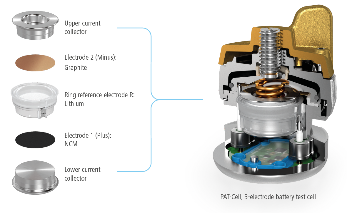
- Finally, test data can’t be better than the 3-electrode test cell used. Different commercial cell designs like the PAT-Cell as well as customized solutions are available and need careful consideration.
Fig. 3: left) Inside components of the 3-electrode PAT-Cell; right) Cut-away view of the cell


Comments are closed.